Showing posts with label arduino. Show all posts

Sunday, August 21, 2016

Not So Fast, 2016!

So, 2016 thought it could sneak by without a post?  Well, too bad.
My unofficial follower count doubled last month, so I owe them all both something for their flappable support.  Unfortunately, this is it:

I haven't had much time for mackerspacing lately since I decided I wasn't pleased with my old psychological state.  Not sure if I'm completely happy with my new one, but I think it'll do for now.

This seems like a good time to finish one of my unfinished projects... should I complete the Amish Oddyssey game, or the Dartboard?   I flip a coin and the winner is...

Start a new project to unfinish!  I've started salvaging some electronics from the local thrift stores and ordered a crazy multi-servo driver shield from Adafruit that may or may not be the correct tool for the job, but I panicked and ordered it anyway.

I will probably start posting my experiments with servos some time in the next few weeks, months or years.  In your face, 2016.

Tuesday, March 17, 2015

If My Parents Didn't Pay My Friends To Be My Friends...

Another paid poster revives this blog.

I'll try to blog a little, you know, like a real blogger.  But I'm not fooling anybody, and I really have to go to the bathroom, so this will be brief -- if we're lucky.

Last I checked, which was many months ago,  the damn dartboard worked.  I think I may have renamed it "Dartboarduino" or something clever like that.  I printed out new stickers for it and hung it on the wall and threw a few darts at it a couple of times.

I wrote a lame python script that had a simple menu and played a basic around-the-world-ish game.  It wasn't very cool, but proved that the thing worked.  I was running it on a raspberry pi to a small led tv and I think some of it was just too much graphics for the poor little pi.  I meant to get back to the software, but never did.

I also meant to rewrite the duino sketch to do different things with the LEDs, but never did.

I also meant to somewhat formalize the api/protocol/messaging thingies, but never did.

Instead, I started to write an Atari Adventure parody in pygame called "Amish Oddyssey" (see how I did that "odd" thing with the word "odyssey"? get it? ha?)   It looked like this the last time I worked on it a couple weeks ago:
Eli carries the scythe to the open doors of the red barn.

Eli Enters the Red Barn to find Schwartzentruber, the black angus, guarding the hand-made basket and assertively mooing to express her anxiety, which is a direct result of Eli's proximity to the basket.

Eli searches for the key to the white barn in the corn maze.

Eli captures the hand-made quilt from under the nose of Yoder, the seemingly disinterested purple hereford.
I thought, "I'll just finish this game real quick-like and then rewrite the dartboard game and then build my theremin and then write my novel and then direct my movie and then move on with my life."

I also recently received a top secret message from google saying that google code hosting is ceasing to be, and I will need to move my code somewhere else, like github.  Which I will do and I will tell all of you paid posters all about it in a new post, and then in 9 months you can comment here with something like, "This is great.  Keep up the great work.  How great is it? Great." and then you can do the same for the 6000 other blogs with no recent activity.

I'll also put my updated python code on github... and probably the code for this Amish Oddyssey travesty (the cows really "moo," so I have that going for me).

Must. Pee. Now.


Tuesday, July 8, 2014

Re-V

Just a quick note to myself to say that I re-completed the hardware... transplanted the contact sheet from another board without major incidents.  I really fried the perfboard where the 20-pin ribbon connector attached...through desoldering the old and resoldering the new.... and I broke the ends of a couple wires from the shift registers bending them into place, switching a couple of the wires in the process... but a quick edit to the duino sketch put everything back in order.

Another "doh!" here.... I had no experience with these ribbon connectors, so I was afraid to mess with them too much.  After I desoldered the old one from my perfboard circuit and while moving the new one from the other board, I realized that the ribbons slide in and out of the connectors quite easily. The big DOH! was that I could have simple left the 20-pin connector from the other board and just switched out the ribbons much more quickly, easily and without the heightened danger of screwing up what was working.

Despite that big miss, I removed the ribbons while I was soldering the connector to the board, so I wouldn't melt the new contact sheets in the process.  I also applied a little hot glue to the connector to hold it in place while upside down when soldering, which made it easier and may have been necessary since I desoldered most of the solder pads along with the solder, so I couldn't really solder the pins securely in place by solder alone.

Oh, almost forgot... I also used the speaker from the new board, which is much smaller than the other.  Instead of soldering the connecting wires, I twisted and taped them.  I also taped the speaker itself into the cavity since it is too small to be held into place by the screws for the factory speaker.

Whatever I did and however I did it, it worked well enough - at least for now.  The board passed regression testing with my serial test python script and then passed some spot-checked dart hits after closing everything up in the case.

I put some black electrical tape around the button holes out of which the LEDs emerge.  This looks a little cleaner and hopefully will protect the perf board from some dust and maybe any stray darts --- although I'd like to find something else to cover the LEDs for dart protection.  I also printed some small labels for the LEDs and a big label for the big window in the middle.  I might revisit these for aesthetic reasons -- I was happy just to get them almost lined up on the label sheets using Open Office Writer.

I hung the thing on my wall with a couple screws and started another test python script using some pygame menu code I found.  I checked it all in to git and am updating the pi as I type so I will port it over and take it for a test run.  Maybe I'll try to make a vid and start a dumb you tube channel as a companion to my dumb blog.

I have some more pics to post here and I still need to update the circuit diagrams to reflect the current circuit and duino sketch.  But, hey, I REALLY finished the hardware... something I wasn't sure I could pull off.  I know I can handle the software, so "Woo Hoo."

Sunday, June 29, 2014

Fixing A Hole Where The Rain Gets In And Stops My Mind From Wandering, Where It Will Go

Did some testing and troubleshooting and fixing today.  The results are encouraging.

I updated my sketch to output the row and column when a hit is detected, and I found out a few interesting things about the issues I reported to myself yesterday.

Firstly, only the red "Server Connection" LED is not working.  The yellow and green light up as instructed when a connection is established.

Secondly, all the number wedges were registering hits today, only the second half of the triple ring was not.

So I charted out all the row/column pairs for each hit combination and updated my matrices in the sketch to match.  A retest found that all hits were registering correctly, except: the second triple ring remains silent and the 18/19 pair stopped registering.

Glancing at the perfboard and ribbon connector, I quickly found the problem with the triple ring... the 7 outputs from the dartboard start on the second pin.  I connected the shift register to pins 1-7 when I should have connected them to pins 2-8.  An easy fix, I will just solder in another small wire connecting pin 1 to pin 8... this also explains why the single/double/triple/bull portion of the matrix was off by 1 in every case. Doh!

The 18/19 pair of wedges may be a precarious solder.  It is the first pin in the second row of the ribbon connectors, and I was flipping the perfboard over and back to inspect the connections, so it is possible that I have been disturbing this joint in the process.  I will de- and resolder this connection, and inspect the other end of the connection at the shift register to see if that may be where the problem actually lies.  I can imagine some of these connections breaking when the board is actively pummeled by darts, so I will be sure to generate the proper documentation that details what shift register pins goes to which dartboard ribbon pin, and what row/column and point/multiplier these match -- if one stops registering, I will be able to find the solder joints quickly and easily.

Finally, I will test the connections to the red server connectivity LED and test the LED itself to see why it is not functioning properly.  To be honest, I will consider this project a success even if this one LED doesn't work, so put that in your pipe and don't smoke it because smoking is a health risk.

On another front, I downloaded some free circuit board design cad software and created the dartboard circuit.  It is a mess.  I need to seriously reconsider the layout to optimize the traces because there is so much crossover in this layout.  The circuit has some layout restrictions due to the location of the LEDs, the location of the ribbon connector and to some extent the orientation of the boarduino.  Unfortunately the software I am using does not appear to have an option to automatically route the copper or optimize the layout.  Also unfortunate is that the other free software that does have this option also has restrictions on the board size -which my circuit exceeds.

I will keep looking for other softwares and maybe try to defeat the limitations by trying to export from one into another.  Fear ye not, I will surely keep all of you updated on this topic, so there is no need to flood the comments section nor my inbox with all of your complaints.  Gee whiz.

Saturday, June 28, 2014

Moment of Truth; Drum Roll, Please; It's...

This story is longer than it should be, but... well, there is no "but."

Finished all the soldering, finally.  left the ribbon connector for last and thought it would be much more difficult than it was.  the soldering was probably not the best in some places, but it is done.

So I had low expectations when I plugged the USB cable into the duino and then into the laptop.  The red LED signifying a USB connection lit up on the duino, but Windows wouldn't recognize it.  I fiddled with a few whatnots and whatevers with no luck. I was convinced that I had a fatal short that fried the processor and was mentally preparing myself to find a new hobby.

I reinstalled the Arduino IDE and drivers and tried plugging in again, this time both of my yellow LEDs lit up for a minute or so, then all of my LEDs turned on and off somewhat randomly before staying off.

I should mention that between my original breadboard prototype and this perfboard version, some of the pins were changed, so I had to change around the code to account for this.  But when I plugged in, the duino was still running the old code, which probably explains the LED madness.

I uploaded the latest sketch and fired up the serial monitor in the IDE.  The "play state" LED set had red lit up but the "Server connection" LEDs were all off.

I typed "C" into the serial monitor, and the dartboard echoed "C" back, yet no LED action. "Q" got an "X" response.  A good sign that the duino wasn't fried and serial communication was functioning.  "P" got an echoed "P" and the play state LEDs went to yellow and then to green, a very good sign. Another "Q" inquiry prompted a "P" response.  Splendid, but now the big test... The Board!

A few random presses on the board resulted in serveral "H"s hollering back from the board to the serial monitor.  This revealed the second issue: the"H"s should have been followed by the point value and multiplier of the wedge being pressed. Soon I identified two more issues: one of the two halves of the triple ring was not registering, nor was one pair of numbers.  Other than that, everything else seems to work!

I consider this a victory.  I have a few relatively minor things to track down... The missing points and multipliers are likely a software bug introduced when the pins were switched around...probably the same with the second set of LEDs, since at least some of them were working to some extent under the original code.  Fixing this may also fix one of the other board hit problems.  I suspect a bad solder may be the cause of one of these things, but this should not be very difficult to track down and fix.  Oh, and I just need to wire up the speaker, but that's hardly a big deal.

It's pretty hard to believe that in a few days this thing could be hanging on the wall and all I have left is the game software (which will probably never be"done")...and not quite the end of June
- almost, but not quite.

Sunday, April 6, 2014

Perf Board Diagrams

The diagram I made last night is very cluttered, so I broke it out into a series of specific diagrams that are easier to follow:
The full rats nest

Parts:
  • 2 x 74HC595 Serial-Parallel Shift Register
  • 1 x 74HC589 Parallel-Serial Shift Register
  • 6 x 5mm LED 
    • 2 x red
    • 2 x yellow
    • 2 x green
  • 15 x Resistor
    • 1 x 100 Ohm
    • 6 x 220 Ohm
    • 8 x 10 k-Ohm
  • 1 x Arduino
  • 1 x Electonic Dartboard
    • 1 x 20 pin Ribbon Connector in 2 rows of 10
    • 1 x Small Piezo Speaker


Here is the Shopping List exported from Fritzing:
AmountPart TypeProperties
1Piezo Speaker
1Generic shrouded header - 20 pinspackage THT; hole size 1.0mm,0.508mm; row double; form ♂ (shrouded male); pins 20; pin spacing 0.1in (2.54mm)
2Green LED - 5mmpackage 5 mm [THT]; leg yes; color Green (555nm)
2Yellow LED - 5mmpackage 5 mm [THT]; leg yes; color Yellow (595nm)
2Red LED - 5mmpackage 5 mm [THT]; leg yes; color Red (633nm)
1Arduino Micro (Rev3)type Arduino Micro (Rev3)
1100 Ω Resistorpackage THT; tolerance ±5%; bands 4; resistance 100Ω; pin spacing 400 mil
810k Ω Resistorpackage THT; tolerance ±5%; bands 4; resistance 10kΩ; pin spacing 400 mil
6220 Ω Resistorpackage THT; tolerance ±5%; bands 4; resistance 220Ω; pin spacing 400 mil
174HC589package DIP16 [THT]; type 74HC595; variant variant 1
274HC595package DIP16 [THT]; type 74HC595


Voltage (red) and Ground (black)

ColorComponentConnectionPinComponentConnectionPin
Red'duino5v5v>74HC589vcc16
>74HC595-1Master Reset10
>vcc16
>74HC595-2Master Reset10
>vcc16
Black'duinogndgnd>74HC589gnd8
>Output Enable10
>74HC595-1gnd8
>Output Enable13
>74HC595-2gnd8
>Output Enable13
>LED (x6)Cathode-
>Piezo SpeakerNegative Terminal-
>10k-Ohm Resistor (x8)
[pull-down]


Shift Register Control:
Shift Clock (blue), Latch Clock (yellow) and Parallel Load (white)

ColorComponentConnectionPinComponentConnectionPin
Blue'duinodigital 5d5>74HC589Shift Clock11

digital 10d10>74HC595-1Shift Clock11

>74HC595-2Shift Clock11
Yellow'duinodigital 6d6>74HC589Latch Clock12
digital 11d11>74HC595-1Latch Clock12
>74HC595-2Latch Clock12
White'duinodigital 4d4>74HC589Parallel Load13

Serial to Parallel - 'duino to Dartboard:
Serial In from 'duino (orange), Serial Daisy Chain (green), Parallel Out to Dartboard (purple)

ColorComponentConnectionPinComponentConnectionPin
Orange'duinodigital 9d9>74HC595-1Serial In14
Green74HC595-1Serial Out9>74HC595-2Serial In14
Purple74HC595-1Parallel Data Out15, 1-7>DartBoardRow 1: 1-81-8

74HC595-2Parallel Data Out6-7>DartBoardRow 1: 9-109-10
Parallel to Serial - Dartboard to 'duino:
Parallel In from Dartboard (brown), Serial Out to 'duino (orange)


ColorComponentConnectionPinComponentConnectionPin
Orange'duinodigital 7d7>74HC589Serial Out9
Brown74HC589Parallel Data In1-7>DartBoardRow 2: 1-71-7


Parallel Data In15, 1-7>10k-Ohm Resistor (x8)
[pull-down]

LEDs and Speaker:
Parallel Out to LED (rgb), 'duino to Piezo Speaker (pink)

ColorComponentConnectionPinComponentConnectionPin
RGB74HC595-2Parallel Data Out15, 1-5>220 Ohm Resistor (x6)

Pink'duinodigital 8d8>100 Ohm Resistor

Silver220 Ohm Resistor (x6)
>LED (x6)Anode+
100 Ohm Resistor>Piezo SpeakerPositive Terminal+


Follower Hoax and Winter Sucks

OK, I think the whole follower thing was a hoax.  Probably someone hired to try to keep bloggers posting or something.  whew!  Things are going to be a lot easier now that nobody is watching again.

I was going to get a lot done over the winter, but winter sucks.  No motivation.  Winter's still trying to linger, but spring is squeezing in enough to matter. So I got a little inspired tonight.

Downloaded the latest version of Fritzing and whipped up an "accurate" perf board diagram:

Well, the "no motivation" thing wasn't entirely true.  I did spend a little time messing with Pygame and OpenGL, 'cause when you are making progress on a project and need to focus on its tasks to make the project a success, it's always a good idea to start more projects.

Sigh.  I'll probably end up posting about the "new" game projects.

Me out.

Sunday, December 8, 2013

Under Pressure

Wow.  A follower.  Now I know exactly how Jesus feels, soooo much pressure.

I did a little more soldering in the past 3 months, but not much.  I am a little down on my soldering skills and intimidated by the reality of soldering it all together.

Hopefully The Follower will encourage me to overcome my fears and inhibitions and soldier/solder on.

My solution to the lack of headroom for the duino in the dartboard case was to order a brand spankin' new boarduino and assemble it without the socket, so the chip sits lower and it all fits in the case.  Not only does  this solve this stupid problem, it also means I have another arduino to play with while this one is busy playing darts.

I soldered the new duino to the perfboard along with all the wiring for the LEDs and the ribbon connector, and most of the grounds.

Next would be the 5v wiring from the duino.  I was thinking - soldering would be so much easier with 3 arms, so anyone who hasn't gotten me a xmas present yet... hint, hint.

I am not certain that all of the connections are wire-to-wire and might be relying on the solder too much in some cases.  Maybe I'll try to head down to the neighborhood hackerspace or makerspace or whatever we have here and get some advice and some help fixing some of the joints that might need fixing.  I have the feeling my current board would be on the cover of "How Not to Solder Your Crappy Project."

I thought about the game engine a little but haven't made much progress there.

I also picked up another cheap-ass electronic dartboard from the local sporting goods store in case I totally ruin this one, or in case I get this working and want to mass produce them (does 2 constitute a mass?).  My local Target just started stocking one for $15 in case things get nutty one way or the other.

This thing has been sitting right next to me on my desk all this time, I just need to do it.

It's been so long since my last post and I didn't go back and read any of them, so I might be repeating some things here.

Hopefully my next post will be soon and hopefully it will report some real progress.


Wednesday, September 18, 2013

Slow Going Slow

Here is a much anticipated update for my 0 followers and 0 page hits per day.

I laid out the perf board and decided to commit... so I soldered the LEDs, resistors and sockets to the board.

Here is a photo with my rough draft, rats nest wiring diagram. The LEDs are on the other side so they poke out through the 6 holes in the front of the dartboard where the buttons used to be.


 I need to go back to my nice Fritzing diagram to make sure I have everything going to the right place.  I kinda reversed the sides of the duino, so I'll have to update the sketch code to use some different pins, but shouldn't be a big deal... as long as I get the dartboard ribbon connectors in the right order, everything else should be easy enough to adjust.

3 challenges:
1) wiring this up without screwing up
2) the USB mini connector was too large to fit inside the dartboard case when plugged into the duino the way i have it set up
3) since i used a socket for the microprocessor on the duino, this board is a little too tall, so the back cover of the dartboard won't go on

My plans:
1) don't screw it up
2) I bought a left-angle mini USB cable from Star Tech that fits perfectly
3) ugh. I guess I'll cut a window out of the cover and use spacers or something.  Maybe I'll think of something else.  I'll have to consider that it has to hang back up flush against a wall and get hit by darts.

Still need to work on the pygame.

Thursday, September 12, 2013

LED LED LED LED LED LED

I dug up 2 red, 2 yellow and 2 green LEDs, 6 220 Ohm resistors and added them to the dartboard interface.  They are wired to the remaining 6 output pins on the second of the daisy chained 74HC595s.

Then I updated the duino sketch to light them up as status indicators: one set to indicate that the board is connected to the game server and the other to indicate that the game is being played.

I loosely tied these to the existing gamestate and command processing functionality, so both are red by default.  The connected indicator goes to yellow for 1 second when a connection command is received from the game server, then to green when the gamestate goes to stopped.

The playing indicator goes to yellow for a second when a play command is received and then to green when the gamestate is playing.... when playing, these are set along with the matrix row being pinged in the game loop.

So I added these variables:

// status light shift register values (logical and with shiftRows1)
byte connectedRed = 1;
byte connectedYellow = 2;
byte connectedGreen = 4;


byte playingRed = 8;
byte playingYellow = 16;
byte playingGreen = 32;

which work together with these:

// data to send to shift register for each board row/pin
byte shiftRows1[10] = {64,128,0,0,0,0,0,0,0,0};
byte shiftRows2[10] = {0,0,1,2,4,8,16,32,64,128};

I added a new method to set these LEDs:

void setStatusLEDs(byte state) {
  boolean setLEDs = false;
  byte connectedStatus = 0;
  byte playingStatus = 0;
  
  switch (state) {
    case IFACE_HIT:
      connectedStatus = connectedGreen;
      playingStatus = playingYellow;
      setLEDs = true;
      break;
    case IFACE_CONNECT:
      connectedStatus = connectedYellow;
      playingStatus = playingRed;
      setLEDs = true;
      break;
    case IFACE_DISCONNECT:
      connectedStatus = connectedRed;
      playingStatus = playingRed;
      setLEDs = true;
      break;
    case IFACE_PLAY:
      setLEDs = false;
      break;
    case IFACE_STOP:
      connectedStatus = connectedGreen;
      playingStatus = playingRed;
      setLEDs = true;
      break;
    default:
      setLEDs = false;
  }
  
  if (setLEDs) {
    // take the shift out latchPin low to shift it out
    digitalWrite(LATCH_SIPO, LOW);
    
    // shift out the bits (assume we're connected and playing if we're doing this at all):
    shiftOut(DATA_SIPO, CLOCK_SIPO, MSBFIRST, connectedStatus + playingStatus);
    shiftOut(DATA_SIPO, CLOCK_SIPO, MSBFIRST, 0);
    
    //take the shift out latch pin high so the voltage is sent
    // to the next row (or none if looking at the first 2 rows):
    digitalWrite(LATCH_SIPO, HIGH);
  }
}

Which I call in the main loop if the gamestate isn't play:

// the loop routine runs over and over again forever and ever and ever:
void loop() {
  if (gameState == IFACE_PLAY) {
    // check for a hit
    for (int row=0; row < 10; row++) {
       setSipoRow(row);
       processPisoColumns(row);
    }
  }
  else {
    setStatusLEDs(gameState);
    delay(1000);
  }
}

If the gamestate is playing, I added the green lights to the shiftout that iterates over the matrix rows:

// sets the SIPO shift register to power the correct row
void setSipoRow(int rowNumber) {
  // take the shift out latchPin low to shift it out
  digitalWrite(LATCH_SIPO, LOW);
  
  // shift out the bits (assume we're connected and playing if we're doing this at all):
  shiftOut(DATA_SIPO, CLOCK_SIPO, MSBFIRST, shiftRows1[rowNumber] + connectedGreen + playingGreen);
  shiftOut(DATA_SIPO, CLOCK_SIPO, MSBFIRST, shiftRows2[rowNumber]);
  
  //take the shift out latch pin high so the voltage is sent
  // to the next row (or none if looking at the first 2 rows):
  digitalWrite(LATCH_SIPO, HIGH);
}

And when a command is processed which changes the gamestate, i set the lights to yellow for a second when transitioning between red and green:

// automatically called between loops when serial data is available
void serialEvent() {
    switch (Serial.read()) {
      case IFACE_QUERY_STATE:
        Serial.print(gameState);
        break;
      case IFACE_CONNECT:
        if (gameState == IFACE_DISCONNECT) {
          setStatusLEDs(IFACE_CONNECT);  // sets connected LED to yellow for a sec
          delay(1000);
          gameState = IFACE_STOP;
          Serial.write(IFACE_CONNECT);
        }
        break;
      case IFACE_DISCONNECT:
        if (gameState != IFACE_DISCONNECT) {
          setStatusLEDs(IFACE_CONNECT);  // sets connected LED to yellow for a sec
          delay(1000);
          gameState = IFACE_DISCONNECT;
          Serial.write(IFACE_DISCONNECT);
        }
        break;
      case IFACE_PLAY:
        if (gameState == IFACE_STOP) {
          setStatusLEDs(IFACE_HIT);  // sets play LED to yellow for a sec
          delay(1000);
          gameState = IFACE_PLAY;
          Serial.write(IFACE_PLAY);
          playCharge();
        }
        break;
      case IFACE_STOP:
        if (gameState == IFACE_PLAY) {
          setStatusLEDs(IFACE_HIT);  // sets play LED to yellow for a sec
          delay(1000);
          gameState = IFACE_STOP;
          Serial.write(IFACE_STOP);
        }
        break;
      default:
        break;  
    }
}

The updated sketch is in git.

I also downloaded Fritzing to try to make some nicer circuit diagrams and came up with this one for the dartboard interface:


They didn't have a part for the boarduino, so I used the Arduino Micro.  They didn't have a part for the 74HC589, so I created my own, based on the 74HC595 included in the core parts list.  I used Inkscape to work on the SVG files required for the Fritzing parts.  The Fritzing diagram and the custom part are both in git.  I started to work on a custom USB Boarduino part but don't know if I will have the time and patience to finish it.

I think Fritzing is beyond cool.

I also cut down my perfboard/pcb to the same size as the original in the dartboard, marked off the mounting screws and posts from the original and used an x-acto to make 4 holes for the posts and screws on either end.  It fits rather nicely, so now I just need to figure out how to fit all my components on there and wire it up.


Wednesday, September 11, 2013

Mmmmmmm, Pi - Another Milestone

Got the Raspberry Pi yesterday.  I had already downloaded an installation disk image (NOOBS) and saved it to an 8GB sans disk (following the quick start guide).  It was easy as.... well, something very easy.

When I got the Pi, I plugged in keyboard and mouse to 2 USBs, HDMI from Pi to TV, and network cable... then the mini USB power adapter.  It started right up and went through configuration screens.  I enabled SSH and changed everything from the UK to my locale and changed my password, then did the updates.  Everything worked just swell.

It already has Python installed and Pygame and git.  I opened a terminal window and installed the python package manager, pip:

sudo apt-get install python-pip

Then the python web framework, Flask, since I think I might use this to interface with smartphones/pads as controllers at some point:

sudo pip install flask

Then I added my git credentials to my .netrc file.  I used the same ones that I put in my windows _netrc file in an older post.  Something like:

cd ~
echo "machine code.google.com login me@gmail.com password [GeneratedPassword]" > .netrc
chmod 600 .netrc

Then added a folder to store my code and cloned my git repo there:

mkdir Code
cd Code
git clone https://TimKracht4@code.google.com/p/no-arms-darts/ 

So then I wanted to try to see if I could just plug in the dartboard via the arduino and run it on the PI.  I needed another USB port for that, so I got out a powerd USB hub, plugged it into the Pi and plugged the keyboard, mouse and arduino into the hub.  I loaded up the python IDE, IDLE,  and opened the serial test script and ran it.  It complained because it couldn't find the Serial module... so I opened the lightweight web browser, Midori, and tried to download the PySerial tarball, but I kept getting empty files.... so I tried pip, something like:

sudo pip install pyserial

Which did the trick.  so I went back to IDLE and tried running the code again.  This time it complained about not being able to find the "COM5" serial port.  Makes sense since COM5 is on my windows laptop.  To find out what pi port the duino was connected to, I first unplugged the duino from the USB hub, then checked out what all was in the /dev folder for tty connections:

ls -alt /dev/tty*

Then I plugged in the duino, waited a few seconds and ran the command again.  The second time around there was a new entry, /dev/ttyusb0, so I figured this was the guy.  I modified the script like so:

ser = serial.Serial("COM5", 9600) # windows
ser = serial.Serial("/dev/ttyusb0", 9600) # *nix

Saved and ran it again and then saw the output scroll as the Pi connected to the duino, then the dartboard speaker beeped "Charge!" when it entered play mode, then correctly reported what segments I pressed on the dartboard contact film matrix thingy.

So another milestone, I successfully (and quite easily) ported the python code from my windows laptop to my Raspberry Pi and have both talking with the duino/dartboard circuit.

Just for kicks, I loaded my Jumpman intro into IDLE and it ran flawlessly.

Next steps: hardware=cut perfboard/pcb down to size and move breadboard prototype over to it.  considering adding LED indicators where the 6 game buttons are --- maybe a couple RGB leds, one for connection to the game server (red not connected, yellow/orange connecting, green connected) and one for play mode (red stopped, orange paused, green playing) and then 4 more LEDs to do whatever with.  Or maybe instead of 2 RGB, just 2 red, 2 orange, 2 green and use 3 separate indicators for each state... that will tie up all 6 button holes with something that is reasonably useful and I won't have to think of something else to use LEDs for, like wasting time with blinking patterns or something... although I know where you can find some sweet LED blinking code. So if I get the pcb built, then screw it into the dartboard case and close it up and hope it doesn't fall apart when I start throwing darts at it.

Next steps: software=still need to jump in and code the game engine in pygame.  Have been jotting down ideas here and there, but now is the time to act, now is the time to code. Need to try to convince myself to use a simple, working design and refactor bells and whistles later. I think I want to try to auto-detect the serial port that the duino is on as a first step, then do a simple game menu maybe, and then the game play for a simple game, like around the clock.

l8r

Saturday, September 7, 2013

Python Serial Talkies, Interface Milestone 2

I tweaked the arduino dartboard interface sketch a little bit and wrote a test python script to talk to the dartboard.  I used PySerial to handle the USB port.  It was easy to implement and is working well so far.

I put a little handshake business in there, but otherwise really trust that everything will work just swell all the time.  It worked almost immediately, so I got to spend a long time fiddling with minutia.  

I let it sit for a couple days and then kept noticing the snipped wires from the dartboard's speaker dangling near the small breadboard that attaches to the dartboards ribbon connector.  So I found the Arduino tones example, wired the speaker to the breadboard, grounding one and sending the other to arduino digital pin 12, through a 100 Ohm resistor and added a generic playMelody procedure in the interface sketch.

// based on the arduino tones example, plays the given melody
void playMelody(int melody[], int noteDurations[], int notecount) {
  // don't even try to play nothin' if we don't got no speaker
  if (HAS_SPEAKER) {
    noTone(SPEAKER_PORT);
    
    // iterate over the notes of the melody:
    for (int thisNote = 0; thisNote < notecount; thisNote++) {
  
      // to calculate the note duration, take one second 
      // divided by the note type.
      //e.g. quarter note = 1000 / 4, eighth note = 1000/8, etc.
      int noteDuration = 1000/noteDurations[thisNote];
      tone(SPEAKER_PORT, melody[thisNote], noteDuration);
  
      // to distinguish the notes, set a minimum time between them.
      // the note's duration + 30% seems to work well:
      int pauseBetweenNotes = noteDuration * 1.30;
      delay(pauseBetweenNotes);
      
      // stop the tone playing:
      noTone(SPEAKER_PORT);
    }
  }
}

Then a playCharge procedure which is called when the interface changes to the play state.

void playCharge() {
  int notes[] = {NOTE_G3, NOTE_C4, NOTE_E4, NOTE_G4, NOTE_E4, NOTE_G4};
  int durations[] = {8, 8, 8, 4, 8, 2};
  int noteCount = 6;
  
  playMelody(notes, durations, noteCount);
}


...
      case IFACE_PLAY:
        if (gameState == IFACE_STOP) {
          gameState = IFACE_PLAY;
          Serial.write(IFACE_PLAY);
          playCharge();
        }
        break;
...

It's totally awesome.

I ordered me a raspberry pi and will be working on the pygame dartboard game engine.

Monday, September 2, 2013

Inside the Board, Interface Milestone 1


Finally got around to opening up the dartboard.


It was pretty much what I expected based on the other projects I have seen... 2 clear plastic sheets with conductive patterns printed on them.  An insulator sandwiched between them with holes allowing the plastic sheets to make contact when pressed together.


The dartboard wedges are really big plastic buttons that press these sheets together to make contact, registering a hit.

 The sheets terminate in a pair of short ribbon cables crimped to a ribbon connector which is soldered to the dartboard's small pcb brain. The pcb has a small lcd display, 2 sets of rubber buttons and wires running to a small speaker, an ac power adapter jack, and a battery compartment.


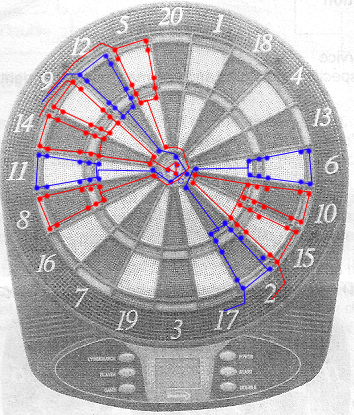
What I didn't expect was the configuration and layout of the 2 contact sheets.  I was hoping for something like a 10x10 matrix, but instead it is a 7x10 matrix.  This means that the inner and outer single-score wedges are wired together and pretty much eliminates some of the games I wanted include.  Oh well.  Maybe I'll hack the sheets to split them into separate connections for v2.

The way these are wired... the board is split into 2 halves: from the 9 wedge clockwise around to 10 and then from 15 around to 14.  The sheet with 7 wires has 3 connections on each half - 1 each for the single, double and triple segments.  The 7th connection on this sheet is for the bulls-eye.  The other sheet has 10 wires... each wire goes to 2 wedges, one on each half of the board, and with 2 wires also connecting to the bulls-eye - one to the single bull and the other to the double.


So when you hit a triple 20, you hit a wire connected to both the 20 and 16 wedges on one sheet and you hit a wire connected to the triple ring on the 9 through 10 half of the other sheet; or row 6, column 0; or boardMatrix[6][0].  Should be easy enough to hook this thing up to the duino, huh?


First thing i did was cut the wires to the batteries, ac jack and speaker and unscrew the pcb from case.  Next, I grabbed a soldering iron and solder sucker and desoldered the 20-pin ribbon connector.  This connector also happened to be glued to the pcb, so a combination of rubbing alcohol, screwdriver and needle-nose pliers finished the job.


 There were some solder lumps on the pins still, so I used the iron to pull some of this off and smooth out all the pins so they could fit into a breadboard.


I started out using just one 595 shift register and 2 duino data pins to send a signal to the board's 10 wired sheet, but for some reason i wasn't making any connections from the duino data pins.  The multimeter showed 5v coming from the pins, going into the ribbon connector and even from the conductive sheet, yet when the connection was made from these data pins directly to the dartboard, hardly any voltage was coming out the other side.  I don't know why.  I am curious, but would rather get this working than figure that out... so I just daisy chained another 595 for the other 2 lines and this worked very well. Possibly unnecessary given the available duino data ports,  but so it goes and so it goes and so it goes.

The final circuit has the duino activating "rows" one at a time in sequence on the 10 side, using the daisy chained 595 serial-to-parallel shift registers.  Then the duino checks all 7 "columns" in sequence on the 7 side, through a single 589 parallel-to-serial shift register, looking for a hot wire.  If it finds such a wire, then it stores the row and column that made the connection, and looks up the wedge value and multiplier segment for that row,column.  This row, column is considered to be in a "pressed" state.  The duino continues to loop through the rows and columns and once this hot row,column is no longer hot, it is considered "unpressed" and a message with some details is sent out the Serial.

When the dart hits the board, the button is pressed for a whole bunch of cycles and we only want to treat it as a single hit.  That's why I just keep track of what was hit and only consider it to be really hit when the button is no longer pressed.  Other projects I have seen just run a delay command when a button press is detected, but I like this unpressed approach better.  I might try a 2d array to hold the state of all buttons, which could be another improvement, but I think this should work for now.

 When I first wired it up, I had a few wires out of place and some of the wedge/multiplier mappings backwards, but these were easy to track down and fix and the whole thing was pretty simple to implement on both the hardware and software sides.  I tested all buttons manually and everything is in working order.


I think this can be considered a milestone.  Cool beans.

So the first version of the sketch is out on git.


Next hardware step is to move my circuit from the breadboards to a pcb about the same size as the board's original pcb, so I can just screw it into place.  Then I'll want to find an extry long mini usb cable.  I'm going to try to find a grommet to fit where the ac power jack sits in the dartboard case and have the usb go through there.  I might eventually try to find another small LCD to use to display my own nonsense.... but that's probably not necessary.

Next software step is to conjure some python code to receive these Serial messages and do something useful.  And order a raspberry pi.  My dog has no nose. "How does he smell?"  Awful.

I have some pics I took along the way which I may or may not add later.  This is the worst blog ever, but I'm happy about the progress I made with the dartboard and Arduino interface, so whatevs, b's.